Application: organic fertilizer (poultry and livestock manure), inorganic fertilizer (nitrogen fertilizer, phosphate fertilizer, potassium fertilizer), compound fertilizer, etc.
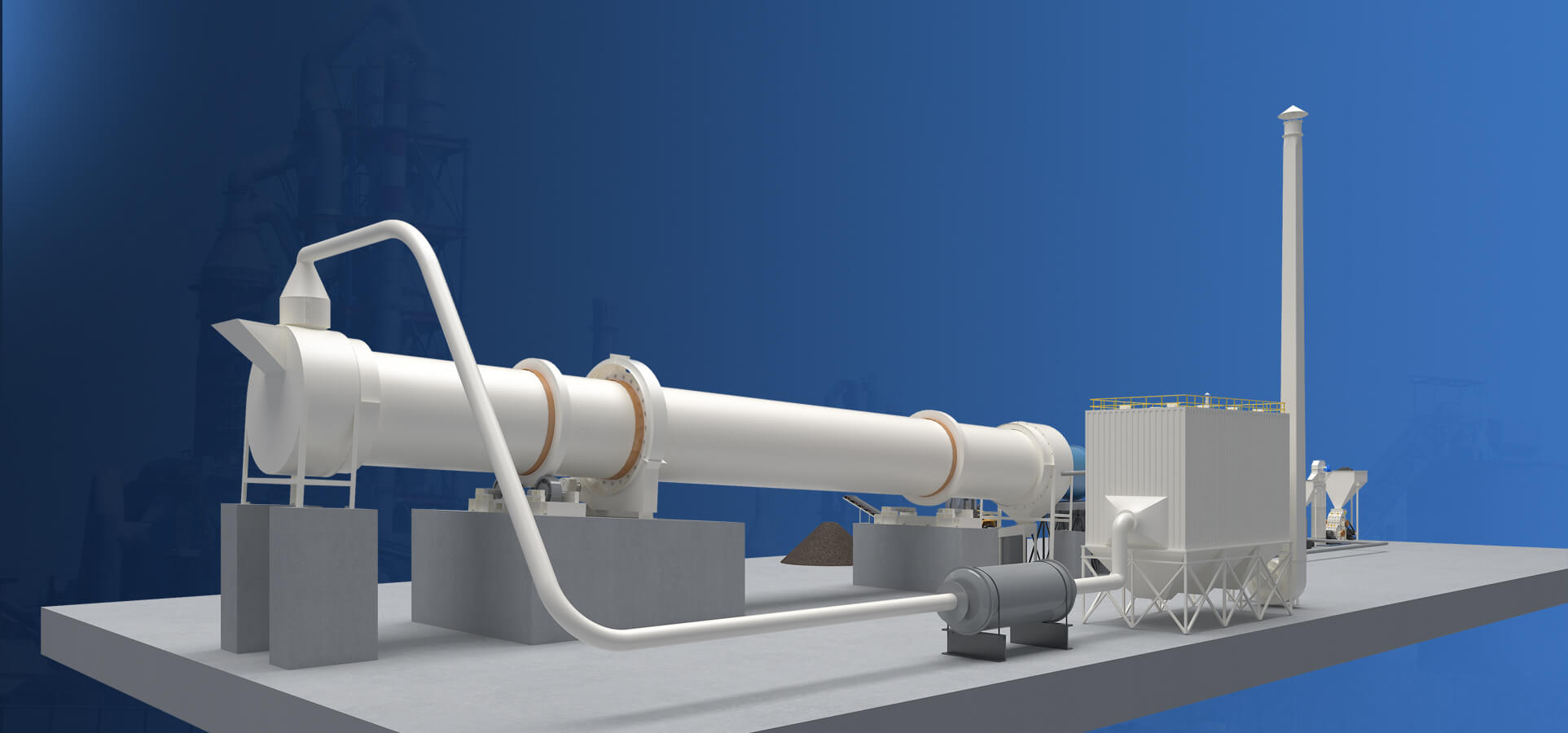
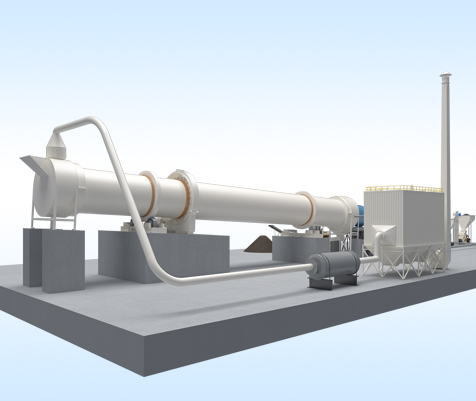
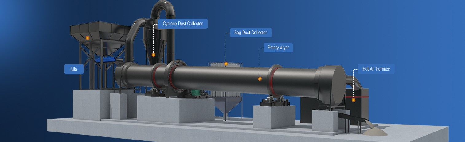
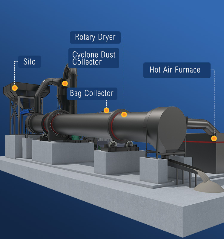
The fertilizer rotary dryer is mainly composed of a rotating body, a lifting plate, a rotating device, a supporting device, a sealing ring, etc. It has the advantages of high efficiency, large processing capacity, fast discharge, low energy consumption, and environmental protection. It can be used for drying organic fertilizers or inorganic fertilizers, effectively reducing the water content of fertilizers.
After drying, the water content of compound fertilizers is reduced from 20%-30% to 2%-5%, and the water content of organic fertilizers is reduced by 10%-40%.
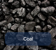
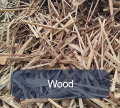
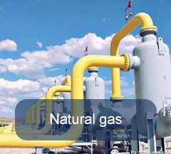
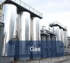
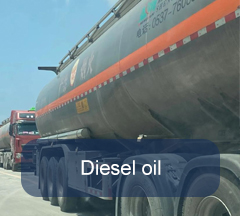
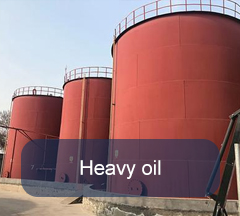
FTM dryers can support multiple heat sources and are easy to switch. The choice of heat source determines the operating cost of the equipment, so the choice of heat source needs to consider safety, environmental protection, material quality requirements, etc. The more common heat sources are mainly divided into three categories: solid fuel, gas fuel, and liquid fuel.
The thermal efficiency is 80% to 90%. The new internal structure strengthens heat conduction of dispersed materials, and eliminates the sticking phenomenon of the inner wall of the cylinder.
Since the heating mode is easy to control, the temperature inside the cylinder and the heat transfer rate of the partition wall can be kept relatively stable.
The cylinder of the dryer is made of steel material, which has the characteristics of high hardness and high toughness.
The dryer system has good sealing performance, and is equipped with a complete dust removal device, with little dust spillage and a good operating environment.
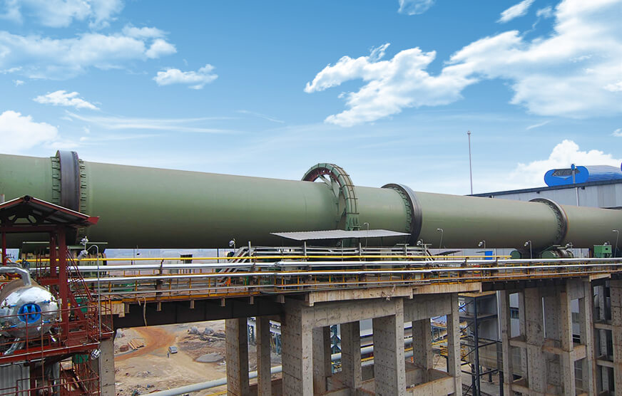
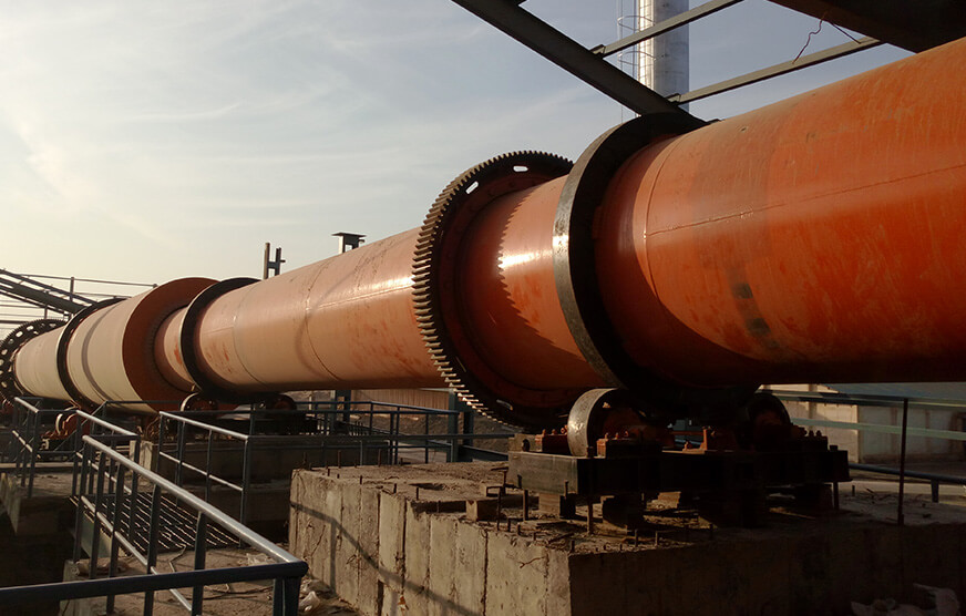
Our drying equipment has been exported to more than 160 countries, such as Indonesia, Malaysia, Ethiopia, Nigeria, South Africa, Pakistan, Egypt, etc. The following is the site of our customer's drying machine.
Capacity: 20 t/h
Processed Material: Sand
Capacity: 10 t/h
Processed Material: Coal
Indirect heat transfer dryer
Rotary Dryer
| Shell diameter × shell Length | Inside diameter of outer shell (mm) |
Inside diameter of inner shell (mm) |
Shell Length (m) |
Shell cubage (m³) |
Shell obliquity | Lifting blade form | Highest inlet air temperature (℃) |
Dimensions (m) |
| Φ1.5×15m | 1500 | 500 | 15 | 20.27 | 3-5% | Lifting form | 850 | 16.2×2.7×2.7 |
| Φ1.5×17m | 17 | 22.97 | 18.2×2.7×2.7 | |||||
| Φ1.5×19m | 19 | 25.68 | 20.0×2.9×2.9 | |||||
| Φ1.8×21m | 1800 | 650 | 21 | 35.91 | 3-5% | Lifting form | 850 | 22.5×2.7×2.7 |
| Φ1.8×23m | 23 | 39.33 | 24.5×2.9×2.9 | |||||
| Φ1.8×25m | 25 | 42.75 | 26.5×2.9×2.9 | |||||
| Φ2.2×21m | 2200 | 800 | 21 | 58.10 | 3-5% | Lifting form | 850 | ---- |
| Φ2.2×23m | 23 | 63.61 | ||||||
| Φ2.2×25m | 25 | 69.15 |
| Shell diameter × shell Length | Inside diameter of outer shell (mm) |
Inside diameter of inner shell (mm) |
Shell cubage (m³) |
| Φ1.5×15m | 1500 | 500 | 20.27 |
| Φ1.5×17m | 22.97 | ||
| Φ1.5×19m | 25.68 | ||
| Φ1.8×21m | 1800 | 650 | 35.91 |
| Φ1.8×23m | 39.33 | ||
| Φ1.8×25m | 42.75 | ||
| Φ2.2×21m | 2200 | 800 | 58.10 |
| Φ2.2×23m | 63.61 | ||
| Φ2.2×25m | 69.15 |
| Spec./m | Shell Cubage | Capacity(t/h) | Installation(%) | Highest Inlet Air Temperature(℃) |
Main Motor |
| Ø1.2×8 | 9 | 1.9-2.4 | 3-5 | 700-800 | 7.5 |
| Ø1.2 ×10 | 11.3 | 2.4-3 | 3-5 | 700-800 | 7.5 |
| Ø 1.5×12 | 21.2 | 4.5-5.7 | 3-5 | 700-800 | 15 |
| Ø 1.5×14 | 24.7 | 5.3-6.6 | 3-5 | 700-800 | 15 |
| Ø1.5×15 | 26.5 | 5.7-7.1 | 3-5 | 700-800 | 15 |
| Ø 1.8×12 | 30.5 | 6.5-8.1 | 3-5 | 700-800 | 18.5 |
| Ø 1.8×14 | 35.6 | 7.6-9.5 | 3-5 | 700-800 | 18.5 |
| Ø 2.2×12 | 45.6 | 9.7-12.2 | 3-5 | 700-800 | 22 |
| Ø 2.2×14 | 53.2 | 11.4-14.2 | 3-5 | 700-800 | 22 |
| Ø 2.2×16 | 60.8 | 13-16.2 | 3-5 | 700-800 | 22 |
| Ø 2.4×14 | 63.3 | 13.5-16.9 | 3-5 | 700-800 | 37 |
| Ø 2.4×18 | 81.4 | 17.4-21.7 | 3-5 | 700-800 | 37 |
| Ø 2.4×20 | 90.4 | 19.3-24.1 | 3-5 | 700-800 | 45 |
| Ø 2.4×22 | 99.5 | 21.2-26.5 | 3-5 | 700-800 | 45 |
| Ø 2.6×24 | 127.4 | 27.2-34 | 3-5 | 700-800 | 55 |
| Ø 3×20 | 141.3 | 30.1-37.7 | 3-5 | 700-800 | 75 |
| Ø 3×25 | 176.6 | 37.7-47.1 | 3-5 | 700-800 | 75 |
| Ø 3.2×25 | 201 | 42.9-53.6 | 3-5 | 700-800 | 90 |
| Ø 3.6×28 | 285 | 60.8-76 | 3-5 | 700-800 | 160 |
| Spec./m | Capacity(t/h) | Highest Inlet Air Temperature(℃) |
| Ø 1.2×8 | 1.9-2.4 | 700-800 |
| Ø1.2 ×10 | 2.4-3 | 700-800 |
| Ø 1.5×12 | 4.5-5.7 | 700-800 |
| Ø 1.5×14 | 5.3-6.6 | 700-800 |
| Ø1.5×15 | 5.7-7.1 | 700-800 |
| Ø 1.8×12 | 6.5-8.1 | 700-800 |
| Ø 1.8×14 | 7.6-9.5 | 700-800 |
| Ø 2.2×12 | 9.7-12.2 | 700-800 |
| Ø 2.2×14 | 11.4-14.2 | 700-800 |
| Ø 2.2×16 | 13-16.2 | 700-800 |
| Ø 2.4×14 | 13.5-16.9 | 700-800 |
| Ø 2.4×18 | 17.4-21.7 | 700-800 |
| Ø 2.4×20 | 19.3-24.1 | 700-800 |
| Ø 2.4×22 | 21.2-26.5 | 700-800 |
| Ø 2.6×24 | 27.2-34 | 700-800 |
| Ø 3×20 | 30.1-37.7 | 700-800 |
| Ø 3×25 | 37.7-47.1 | 700-800 |
| Ø 3.2×25 | 42.9-53.6 | 700-800 |
| Ø 3.6×28 | 60.8-76 | 700-800 |
Focusing on induatrial rotary dryer for more than 40 years, Fote Machinery has provided professional project guidance, equipment production, production line construct, management and operation services for more than one million customers.

We guarantee that our products are all up to standards set for mining machinery.

We will deliver products timely by contract.

We will supply you with installation drawings, specifications and operation manual.

We offer lifetime warranty and components for products.


